Testing of geotextiles and geotextile-related products
Testing of Geotextile and geotextile-related products
The definition of a geotextile, taken from EN ISO 10318-1, is: “planar, permeable, polymeric (synthetic or natural) textile material which may be nonwoven, knitted or woven, used in contact with soil and / or other materials in geotechnical and civil engineering applications.”
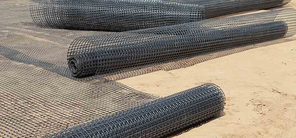
Geotextiles are basically fabrics which are permeable to fluids such as water and gas. Then there are the so called ‘related products’ such as geogrids, geomeshes, geonets and geocomposites.
Geomembranes, or geosynthetic barriers, which is the preferred European term, in contrast to geotextiles (and geotextile-related products) are impermeable to fluids and serve to function as barriers within soils.
BTTG® offer an unrivalled testing service of Geotextiles and Geotextile-related products to manufacturers, consulting engineers, contractors and landfill operators and others. We are able to perform a wide range of mechanical, hydraulic and durability tests using British (BS) European (EN), International (ISO), American (ASTM) and Australian (AS) standards. The tests are co-ordinated and carried out by the High Performance Materials (HPM) department in custom designed premises in Trafford Park, Manchester. The laboratory building contains three separately conditioned laboratories and a large preparation area with a loading bay to handle samples directly from site and from manufacturers.
BTTG® is the UK’s leading laboratory for testing geosynthetic materials and was the first UK laboratory to be UKAS accredited for any geosynthetic tests. BTTG® hold UKAS accreditation to ISO 17025 for an extensive range of geosynthetic tests, including opinions and interpretations. View our schedule of UKAS accredited tests.
Contact us at onestopshop@bttg.co.uk
The principals of commonly performed tests
Where two or more standards have been grouped together under one heading, the test methods are not necessarily identical, nor would they produce the same results, but they follow similar principals of test.
Sampling and preparation of test specimens
BS EN 963; BS EN ISO 9862
This standard establishes general principles for sampling of geotextiles and geotextile-related products and preparation of test specimens from the sample.
Mass per unit area
BS EN 9864; BS EN 965; ASTM D5261; AS 2001.2.13 (AS3706.1)
Specimens of known area are cut from the sample and weighed. Mass per unit area is calculated. This is usually expressed in g/m2.
Thickness
BS EN ISO 9863-1; ISO 9863-2; BS EN 964-1; ASTM D5199; AS 2001.2.15 (AS3706.1)
The nominal thickness is determined by measuring the distance that a movable plate is displaced from a parallel surface by the material while under a specified pressure. The results are usually expressed in mm (at a specified pressure).
Tensile properties / Seam properties
BS EN ISO 10319; BS EN ISO 10321 (seams); BS 6906: Part 1; ASTM D4595; AS 3706-2
Specimens, 200mm wide, are clamped across their entire width with a specified gauge length and pre-tension, and strained at a specified rate until rupture occurs. Tensile strength per unit width (N/mm or kN/m) and extension (%) are measured.
Grab tensile strength
ASTM D4632
The central portion of a rectangular specimen is clamped at a set gauge length and an increasing load is applied at a constant speed until rupture occurs. Grab tensile strength (N/25mm) and apparent elongation (%) are measured.
Puncture resistance
BS EN ISO 12236; BS 6906: Part 4; DIN 54307; ASTM D6241; ASTM D4833; AS 3706.4
Specimens for test are clamped between circular rings with a specified internal diameter and a puncture probe of known dimensions is pushed centrally against and normal to the fabric at a specified speed until failure of the specimen occurs. Push through force (N) and plunger displacement (mm) / elongation (%) (where appropriate) are measured.
Pyramid puncture resistance of supported geosynthetics
EN 14574
This test is used to determine the puncture resistance of a geosynthetic on a rigid support (such as a tunnel lining).
A specimen for test lies flat on an aluminium plate supported by a steel base. A force is exerted on the centre of the specimen by a pyramid-shaped solid steel piston which is attached to a load indicator and is driven at a speed of 1mm per minute, until perforation of the specimen occurs.
Contact between the pyramid and aluminium when perforation occurs, completes the electrical circuit and the push through load is recorded.
Trapezoid tearing strength
ASTM D4533; AS 3706.3
A specimen for test is clamped in parallel jaws of a tensile testing machine, with a specified gauge length, along the nonparallel sides of a trapezoid shape that has been marked on a rectangular specimen with an initial cut. The machine is operated at a constant speed so that the initial tear propagates across the specimen. Results are expressed in N.
Resistance to perforation (Cone drop test)
BS EN ISO 13433; BS EN 918; BS 6906: Part 6; AS 3706.5
The specimen for test is clamped between circular rings with a known internal diameter and a 45° steel cone of given weight is dropped point first, through a specified distance on to the centre of the specimen.
The degree of penetration is measured viewing the specimen from underneath, by inserting a narrow angle graduated cone into the hole. Results are expressed in mm.
Apparent pore size distribution (Dry sieving)
AS3706.7
The pore size distribution is obtained by determining the percentages of each of a number of different sizes of glass spheres which are retained on the geotextile when shaken through it employing the geotextile as the sieve. Sieve size, mass of glass beads, amplitude of shaker and duration are all specified.
Characteristic opening size (wet sieving)
BS EN ISO 12956
The characteristic opening size is obtained by determining the particle size distribution of a graded granular material that is washed through a single layer of geotextile using the geotextile as a sieve. The test specifies a pre-treatment, minimum sieve size, mass of granular material, sieve amplitude and test duration.
The granular material passing through the specimen is combined and a particle size distribution carried out following the guidance given in ISO 2591-1.
Determination of water flow / permeability (normal to the plane)
BS EN ISO 11058;
A constant head of water is applied to the specimen for test that is clamped between circular flanges with a known exposed area. The water passing through the specimen is collected for a given period of time and flow rate / permeability calculated.
Determination of water flow capacity in the plane (transmissivity)
BS EN ISO 12958; BS 6906: Part 7
The flow of water in the plane of the material is measured under varying normal compressive stresses, typical hydraulic gradients and defined contact surfaces (used to model field conditions).
Cylinder Test
Environment Agency Methodology for Cylinder Testing of Protectors for Geomembranes
The test determines the effectiveness of a material in protecting a geomembrane against long term effects of static point loads, under the conditions expected to be encountered at waste management sites. Load is applied through the proposed drainage aggregate and protector material on to the geomembrane, which is supported on a simulated standard subgrade for a specified period of time. The local and incremental strain experienced by the geomembrane are recorded and measured.
Determination of the Long Term Protection Efficiency of Geotextiles in contact with Geosynthetic Barriers
EN 13719
Load is applied through a simulated standard aggregate on to a geotextile specimen, which is supported on a simulated standard subgrade for a specified time. The local strain in the lower surface of the geotextile is measured and used to determine the protection efficiency.
The geotextile specimen sits on top of a lead sheet. As the load is applied through the simulated aggregate the deformation is reflected in the lead sheet. The load is maintained for a period of 100 hours and at the end of the test, the apparatus is dismantled and the lead sheet retrieved. It is examined and the three deformations with the greatest strains selected, measured and calculated.
The test is performed three times at stresses of 300, 600 and 1200 kPa.
Compressive properties
ASTM D1621; BS EN ISO 25619-2
This standard provides information regarding the behaviour of materials under compressive loads. A load, evenly distributed across a whole specimen of known dimensions, is applied at a specified rate and the compressive properties are measured.
Compressive Behaviour
BS EN ISO 25619-1; ASTM D1621
A specimen is placed on the fixed base if a compression machine with an upper loading plate, and a compressive load (either a normal load or a combined normal and shear load) is applied and the change in thickness is recorded with time. Compressive strain and compression creep are calculated.
Tensile Creep and Creep Rupture Behaviour
EN ISO 13431 non UKAS (subcontract)
For the measurement of tensile creep, specimens are loaded with a constant static force, the load being evenly distributed across the specimen width. The elongation of the specimen is recorded continuously for a period of 1000 hours but if the specimen ruptures before 1000 hours the time to rupture is recorded. Tensile creep strain is calculated.
For the measurement of tensile creep rupture, specimens are loaded with a constant static force, the load being evenly distributed across the specimen width, until the specimens rupture. The time to rupture is recorded. Tests are carried out at four load levels between 50 and 90% of the measured tensile strength, testing three specimens at each load level.
The time to creep rupture for each specimen is reported.
Evaluation of mechanical damage under repeated loading. Damage caused by granular materials
EN ISO 10722 non UKAS (subcontract)
This test describes a procedure for damaging geosynthetics in the laboratory to simulate site damage during installation when a geosynthetic is laid between two layers of compacted granular material.
A geosynthetic specimen is placed between two layers of synthetic aggregate and subjected to a period of dynamic loading.
The specimen is removed from the apparatus, examined for any visual damage and then subjected to either a mechanical or hydraulic test to measure the change in properties.
Determination of friction characteristics – direct shear test non UKAS (subcontract)
EN ISO 12957-1
The material for test is submitted to direct shear at its contact surface with standard sand in a shear box.
Under a given normal stress the lower half of the shear box is moved horizontally at a constant rate of displacement, relative to the upper half and the applied horizontal stress is measured at regular intervals, making a note of the maximum force recorded.
The test is repeated at three different normal stresses.
The angle of friction at the sand/ geosynthetic interface is determined by plotting the three points for normal stress against horizontal shear stress, constructing a straight line through these points and recording the slope of the line, in degrees, as the angle of shear stress.
This index test is rarely used but it is commonly modified to simulate site condition, especially where there is a need to know the friction between two or more layers of geosynthetic.
Determination of friction characteristics – inclined plane test
EN ISO 12957-1 non UKAS (subcontract)
This standard describes a method to determine the friction characteristics of geosynthetics in contact with soils, at low normal stress, using an inclining plane apparatus.
This test method is primarily intended as a performance test to be used with site specific soils but may also be used as an index test with standard sand.
The angle of friction for a soil/ geosynthetic system is determined by measuring the angle at which a soil filled box slides when the base supporting the geosynthetic is inclined at a constant speed.
The slipping angle is used to calculate the angle of friction.
Durability Tests
As part of CE Marking of geotextiles and geotextile-related products, the manufacturer is required to make a durability statement relating to the product. The following standard tests are used to assess the durability.
General tests for evaluation following durability tests.
BS EN 12226
The principle of each durability test, is that pairs of specimens of the material to be tested are prepared for tensile tests, in each direction. One of each pair is exposed to the relevant treatment and the other is treated as the control specimen. After completion of the exposure, both sets of specimens are tested and the percentage retained tensile properties calculated.
Determination of the resistance to weathering
BS EN 12224
Specimens are exposed to a light source for a defined radiant exposure (50 MJ/m2) and at recommended temperature and moisture conditions. After this exposure the change in performance is determined.
Determining the microbiological resistance by a soil burial test
BS EN 12225
Specimens for test are buried, in microbially active soil in a dark environment with admission of fresh air and air ventilation for 16 weeks. The moisture content of the soil is controlled and the microbial activity of the soil is also checked during the soil burial test.
After the exposure period, the specimens are recovered from the soil and immersed in an ethanol-water solution for five minutes. They are then rinsed, wiped and left to dry for 72 hours before conducting the tensile tests to assess the % retained strength.
Screening Test Method for Determining the Resistance to Hydrolysis in Water
BS EN 12447
Specimens for test are immersed in de-ionised water at 80 °C for a period of 28, 56 or 112 days. The pH is monitored at least once a week, and if it exceeds 8, measured at room temperature, the water must be replaced. The control specimens are immersed in de-ionised water at 80 ± 1 °C for 6 hours.
All specimens are allowed to dry and condition before tensile tests are made in accordance with EN 12226. The % retained tensile strength is measured.
Screening test method for Determining the Resistance to Oxidation
BS EN ISO 13438
Test specimens are exposed to an elevated temperature in air over a fixed time period, using a regulated laboratory oven.
Polyethlene and polypropylene products are tested at a temperature of 100 ˚C for 28, 56 or 112 days.
The control specimens are exposed at the same temperature as the test for a period of six hours.
The exposed and control specimens are subjected to tensile tests in accordance with EN 12226 and the % retained tensile strength is measured.
Screening Test Method for Determining the Resistance to Acid and Alkaline Liquids
BS EN 14030
Specimens are immersed in two test liquids at a temperature of 60 ˚C for a period of three days. The test liquids used are:
- An inorganic acid (Approximate pH 1.5)
- An inorganic base: (Approximate pH 12.1)
After exposure the specimens are rinsed thoroughly.
The control specimens are immersed in water at 60 ˚C for one hour.
All specimens are then dried and conditioned before tensile tests in accordance with EN 12226 are conducted to measure % retained tensile strength.
Abrasion damage simulation
BS EN ISO 13427
A test specimen mounted on a fixed platform is rubbed by an abradant with specified surface characteristics using controlled conditions of pressure and abrasive action. Resistance to abrasion is expressed as the percentage loss of tensile strength.
For further information, please contact Rob Marshall (+44 (0)161 873 6543 rob.marshall@bttg.co.uk) who will be happy to discuss your requirements.